Electric Motors and Drives (EMD)
As the market for electrified vehicle powertrains develops rapidly, the quest to deliver improved efficiency and performance in electric drive…
SAWsense
Proven sensor technology for highly accurate measurement of torque, force, pressure and temperature.
A wireless, passive, sensing system consisting of three main elements: SAW sensing elements connected to antennas known as RF Couplers mounted on the part to be measured and an electronic interrogation unit called a reader, connected to its stationary RF coupler. The reader generates and transmits an interrogation signal across the RF Coupler to the sensing element. The sensing element is excited by this RF signal creating a Surface Acoustic Wave (SAW) on the surface of a Piezoelectric substrate between the fingers of an interdigital transducer (IDT). The IDT reflects the SAW back to the reader. The frequency of this reflected signal is affected by the physical measurement of either strain or temperature in the sensing element. The reader analyses the received signal and calculates the value of the physical measurement.
In most non-contact, rotating, torque measurement applications the distance between the sensor antenna and the reader antenna should be less than 5mm, and the torque update period can be as small as 100 microseconds or a frequency of 10kHz. For other applications where slower update frequencies are possible larger separation distances are possible up to several metres.


As the market for electrified vehicle powertrains develops rapidly, the quest to deliver improved efficiency and performance in electric drive…

The measurement of torque is common practice in all types of aerospace engines and is used to improve safety, pilot control, and engine reliability.…

Off-highway machinery and Industrial Robotics provides the backbone of many sectors, from mining and construction to agriculture, materials handling,…

Transense has partnered with McLaren Applied for Motorsport torque-sensing systems.
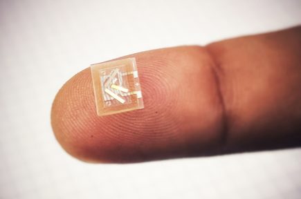
The key part of the SAW sensing system is a small lightweight SAW sensing element made on a piezoelectric substrate. The surface acoustic wave propagates on its free surface between the 2 sides of an Inter-Digital Transducer (IDT). The IDT is a thin-film conductive structure fabricated by a standard photolithographic process which is the same process as used for manufacturing integrated circuits and MEMS devices. The IDT converts electric RF signals, with a frequency of hundreds of MHz, into the mechanical SAW on the surface and due to the piezoelectric effect returns them into a RF signal. If the IDT is surrounded by the Bragg reflecting gratings, in the form of periodic arrays of thin conductive strips, then the energy of the SAW is trapped inside the cavity between the gratings and the SAW device works as a resonator.
When the strain is applied or the temperature of the substrate changes, the SAW velocity changes, the changing SAW velocity creates a frequency shift in the reflected RF signal. This makes the resonant frequency sensitive to strain and temperature, and allows the SAW resonator to be used as a strain and temperature sensing element.
Transense has developed SAW sensing elements having two to three SAW resonators each. For Strain measurement 2 resonators are used at 90 degrees to each other which allows the principal resultant strain between them to be measured. If required the third resonator allows temperature to be measured at the point of measurement enabling calibration offsets to be applied across the full working temperature range of the system.
To turn the SAW device into a practical sensing element its is packaged to protect it from the environment and efficiently coupled to the physical component to be measured. Because it has a lid formed from Quartz, Transense calls its proprietary design of packaged SAW device an "All Quartz Package" or AQP. Transense has developed AQP's for pressure and temperature (up to 150 psi), as well as torque/strain and temperature measurement (up to 500-800 microstrain) within the temperature range of -40˚C to +150˚C. AQP's are especially well-suited for high-volume and low-cost applications.


Transense SAW sensing systems to measure Force, Torque and Pressure rely on the physical measurement of strain on the surface of the component using SAW IDT’s have built-in temperature measurement, which is used to provide temperature compensation in the strain measurement over the operating temperature measurement of the part. Transense SAW Technology is also suitable for the standalone measurement of temperatures in electric motor rotors, high-voltage electrical systems, industrial machinery and engines.
The advantage of SAW technology remains highly robust non-contact sensing systems, which utilise passive SAW sensing elements mounted on the moving component to measure temperature.
The electronics reader, or Sensor Interrogation Unit developed by Transense can wirelessly measure up to five resonant frequencies of the SAW sensing elements in a typical torque measurement system or up to 12 sensing elements in a temperature only measuring system.
A key component of the reader is a Radio Frequency Application-Specific Integrated Circuit (RF ASIC) developed by Transense, which allows a very fast and accurate measurement of the SAW resonant frequencies and reduces the size and cost of the electronics to a level acceptable for high-volume applications. Apart from the RF ASIC, there is another key component, a Digital Signal Processor (DSP) to control the operation of the transceiver, perform spectral analysis of the SAW response, and calculate strain/torque/pressure and temperature.
The standard Transense SAW electronics reader has both analogue and digital CAN and SPI outputs transmitting data up to 6.67 kHz. The accuracy of the frequency measurement is better than 1 kHz at 430 MHz.
Transense has also developed specialised readers with various form factors, multichannel readers with up to eight RF channels and a high-speed reader with a strain/torque update rate of 16 kHz; the fastest available on the market.

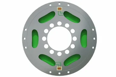
A typical arrangement of the SAW torque sensing system includes one reader, one or two SAW sensing elements bonded to the shaft or any other part, and an RF rotary coupler with a stator playing the role of the near-field reader antenna, and a rotor working as a near-field sensor antenna.
A pair of near-field close-coupled antenna, the stator and rotor, referred as RF rotary couplers, are used to wirelessly transmit the RF signal from the ASIC to the rotating SAW sensors. Transense has developed RF rotary couplers with a planar and coaxial cylindrical geometry for shaft diameters from 10 to 420mm.
The gap between the stator and rotor couples are from 1 to 20mm, and rotational speeds up to 30,000 rpm have been produced, higher shaft speeds are also possible. Most of the RF coupler designs are based on an inexpensive PCB material and can often be used as a standard solution for several different applications.

IndyCar starts torquing with a British accent

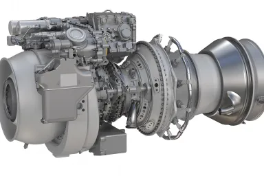
GE, US Army leverage key sensing technology from UK-based Transense for new ITEP - T901 engines

Get an insight into the patented technology we develop through our technical publications

Read further about the benefits of SAW Sensor Technology and how it compares to competing technologies

Questions and answers on our patented Transense Torque and Temperature sensors

The global market for mobile robotics is expanding rapidly. From collaborative robots (cobots) working safely alongside humans, to humanoid robots…

As well as a world-leading force, pressure and torque sensing solutions, Transense SAW Technology is suitable for the standalone measurement of…

Transense Technologies, in collaboration with the transmission and electric motor drive systems development experts at Drive System Design Limited…

Torque sensors form an integral part of modern aerospace control systems, there are several established key applications and new emerging areas where…

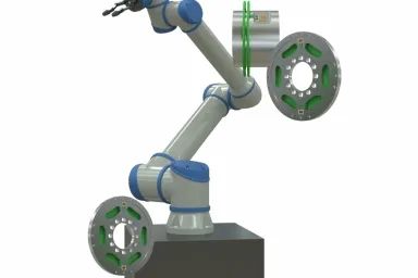
Robotic arms are designed to move payloads and tools, providing a high level of dexterity. They are used in many different applications in the…

As the market for electrified vehicle powertrains develops, so the quest to deliver improved efficiency and performance in electric drive systems…

The global market for robotics is expanding rapidly. With the advent of lower-cost robots that are easier and cheaper to deploy such as collaborative…